TEPCO will do anything to maintain the ‘unforseeable’ theory Nuke Info Tokyo No. 143
– The ‘simulation analysis’ deception technique –
Highly likely LOCA in Reactor Unit 1
If they possibly can, what the Japanese state and Tokyo Electric Power Company (TEPCO) would like to see buried once and for all is the notion that the critical equipment at TEPCO Fukushima Daiichi Nuclear Power Station Reactor Units 1, 2, and 3 (1F 1-3) sustained serious damage from seismic motion unrelated to the ‘unforeseeable’ giant tsunami. The reason is that if it becomes known that even in one of the three reactors critical piping was damaged in the seismic motion and that a ‘loss of coolant accident’ (LOCA), where coolant gushes out from a damaged pipe into the containment vessel, occurred, then the grave issue of ‘earthquake vulnerability of the central structures of nuclear power stations’ would arise, shaking the very foundations of the safety of nuclear power in ‘earthquake country Japan.’ If that happens, the tsunami measures and external power supply measures that are the current government’s basic policy conditions for the resumption or continuation of operations of existing nuclear power plants NPPs will be forced to undergo a fundamental review and it may become impossible ever to resume the operation of Chubu Electric Power Company’s (CEPCO) Hamaoka NPP.
However, the facts cannot be suppressed forever. Judging from the various kinds of data released by TEPCO thus far, there is an extremely high probability that an LOCA occurred in the reactor piping in at least Unit 1 at the time the earthquake struck. Figure 1, based on data released by TEPCO on 16 May, shows in one figure both the changes in the ‘reactor water level’ (the depth of water above ‘top of active fuel’ [TAF]) and the changes in ‘containment vessel pressure’ (Note 1) in Unit 1 following the earthquake. Using this figure, I will describe below the outline of the ‘LOCA sequence’ that I presume occurred in 1F 1.
Note 1: TEPCO released only the ‘absolute pressure’ data, which includes the atmospheric pressure component, for the containment vessel (drywell and [pressure] suppression chamber) pressure, but since the problem from the viewpoint of structural strength is the ‘gauge pressure,’ given by subtracting the atmospheric pressure component from the absolute pressure, this figure uses gauge pressure.
Before the earthquake struck, the reactor water level was 5 m above TAF, but some reactor piping (pipes entering or exiting the reactor, such as the main steam pipe, main feed-water pipe, recirculation piping, ECCS-related piping, and so on) was damaged due to seismic motion, and as coolant began to leak from the damaged piping, by 6 hours and 44 minutes after the earthquake struck, i.e. at 21:30 on 11 March, the reactor water level had descended to a level only 45 cm above TAF (Fig. 1, [1]).
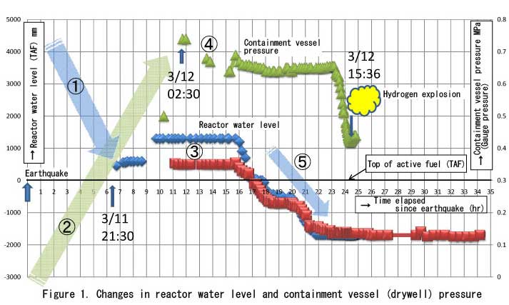
The pressure in the containment vessel during normal operation is almost the same as atmospheric pressure (although the gas inside it is not air; nitrogen is enclosed inside it to prevent hydrogen explosions). Immediately following the earthquake, however, large amounts of coolant at 7 MPa (roughly 70 atmospheres [atm]) began to gush out of the damaged piping, the pressure and temperature inside the containment vessel began to rise gradually, and 11 hours and 44 minutes after the earthquake, i.e. at 02:30 on 12 March the containment vessel pressure rose to 0.74 MPa (about 7.4 atm), greatly exceeding the design pressure (approximately 0.4 MPa, about 4 atm) (Fig. 1, [2]).
Meanwhile, from data released by TEPCO, by almost the same time, 02:45 on 12 March, it is clear that the reactor pressure had declined to 0.8MPa (about 8 atm). Thus, since at about this time the pressure inside the reactor and inside the containment vessel were roughly equal, the leaking of coolant from the damaged piping had slowed, and for several hours after that the reactor water level was almost unchanged (Fig. 1, [3])
Nevertheless, since the pressure in the containment vessel had greatly exceeded the design pressure, steam was beginning to leak from the bolted joint (flange) of the ‘upper lid’ at the top of the containment vessel, causing the pressure inside the containment vessel to gradually subside (Fig. 1, [4]).
Because of this, the pressure balance between the reactor pressure and the containment vessel pressure collapsed, coolant once again began to gush from the damaged piping, and the reactor water level plunged (Fig. 1, [5]). The result of this was that the nuclear fuel rods were exposed far above the surface of the water, finally leading to the melting of the vast majority of them. Large amounts of hydrogen being produced by a ‘zirconium-steam reaction’ within the reactor then gushed out into the containment vessel along with the steam from the damaged piping, and following that, hydrogen, being light, migrated to the top of the containment vessel and finally leaked out into the operation floor through the upper lid flange.
Thus, at 15:36 on 12 March, a hydrogen explosion occurred on the operation floor.
The most puzzling aspect of the accident – Why did the containment vessel pressure exceed the design pressure?
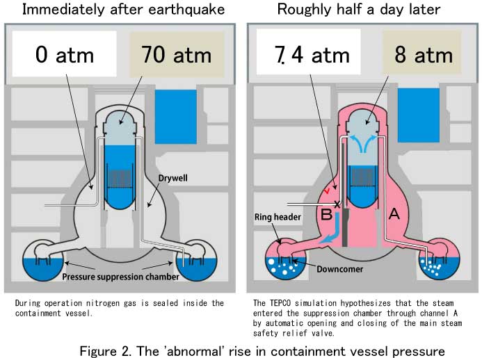
The most puzzling aspect of the 1F 1 accident sequence data is why the containment vessel pressure rose very rapidly from 0 MPa to 0.74 MPa (about 7.4 atm), far above the approximately 0.4 MPa (about 4 atm) design pressure (Fig. 2). I think it is not too much to say that this is the greatest puzzle of the 1F 1 accident. The reason is that the containment vessel design pressure is set to the theoretically presumed greatest overpressure created when the reactor piping with the greatest diameter (in actuality the recirculation outlet pipe) undergoes an instantaneous guillotine break, and then a little more for safety.
I do not believe that a large diameter pipe such as a recirculation outlet pipe experienced a guillotine break at the time of the 11 March earthquake. If such a massive LOCA had taken place, the reactor water level would have dropped precipitously, as if the plug had been pulled out of the bath, but no such phenomenon took place. The LOCA that I assume occurred was, at least at first, a quite unpretentious one. I think it was a relatively small or medium LOCA of this nature: First, a relatively small crack appeared in some reactor pipe, from which coolant began to blow out, and as this crack grew gradually larger, increasing amounts of coolant began to gush out. However, if this is so, then all the more reason to be puzzled about why, in just half a day after the earthquake struck, the containment vessel pressure rose ‘abnormally’ and exceeded the design pressure.
Unresolved safety issue of the Mark-I containment vessel
Already by the early 1970s, General Electric (GE, a US company) engineers were whistle-blowing the so-called Mark-I containment, used in 1F 1-5 as a ‘defective’ containment vessel. This was frequently reported in all Japanese media for some time immediately after the Fukushima Daiichi nuclear power plant accident. The issue raised by GE engineers was later named the ‘Unresolved Safety Issue’ by the United States Nuclear Regulatory Commission (NRC), and in 1980 the NRC published technical guidelines for the issue. What was this unresolved safety issue?
Kindly refer once again to Figure 2. When a pipe breaks and an LOCA occurs, large amounts of steam blow out into the drywell from the crack (marked as B in Fig. 2) and head furiously toward the (pressure) suppression chamber. The steam entering the suppression chamber is at first guided to a doughnut-shaped pipe called a ‘ring header,’ and is then introduced into the water in the suppression chamber through a large number of pipes known as downcomers. When this happens, the volume of the steam is reduced as it condenses into water, and thus the pressure is relieved (‘suppressed’).
However, in fact, ‘before’ the steam passes through the downcomers and enters the water, the nitrogen gas filling the containment vessel is firstly pushed violently down through the downcomers and into the water. Since nitrogen gas does not dissolve in water, the instant it exits the downcomers the nitrogen gas greatly expands in the water (called ‘swelling’). This causes the large mass of water in the suppression chamber to shake violently, both vertically and horizontally. This can result in the ends of the downcomers to come above the water level, failing to introduce the steam into the water correctly. The steam is then ejected into the space at the top of the suppression chamber. The water does not therefore lose volume through condensation and the containment vessel pressure is not relieved (loss of function of the pressure suppression mechanism).
Or perhaps, because of the violent shaking of the water, the downcomers and the ring header were damaged, again possibly resulting in a total loss of function of the pressure suppression mechanism. This issue of the structural strength of the suppression chamber and loss of suppression mechanism brought about by the ‘hydrodynamic loads’ is the NRC’s ‘unresolved safety issue.’
In the case of the 1F accident, the problem was extremely severe, since the extra load of the seismic motion was added to the hydrodynamic loads. The large mass of water in the suppression chamber (1750 tons of water in the case of 1F 1) must have been ‘sloshing’ violently during the main earthquake and the aftershocks, and thus the suppression chamber mechanism may not have been functioning correctly or the downcomers and ring header may have been damaged.
The ‘simulation analysis’ deception technique
It seems to me that an LOCA occurred due to pipe damage; large amounts of steam blew out into the containment vessel (drywell) heading toward the suppression chamber, but due to the hydrodynamic loads and the ‘sloshing’ at the time of the earthquake, the structures were damaged and the pressure suppression mechanism was lost. As a result, steam volume was not reduced through condensation, and thus the pressure in the containment vessel rose to 0.74 MPa (about 7.4 atm), and this is the answer to the ‘greatest puzzle of the 1F 1 accident.’
Meanwhile, on Sunday, 15 May, TEPCO held an emergency press conference to explain that, as a result of a ‘simulation analysis,’ 1F 1 had experienced a ‘meltdown’ (by this term TEPCO apparently meant that molten fuel rods had fallen to the bottom of the reactor) at quite an early stage.
TEPCO did not really need to explain this as it had already become quite obvious to many people that a meltdown had occurred, but perhaps because this was the moment when TEPCO at last ‘formally’ recognized the fact, this meltdown press conference is still accepted by the general public in a positive and favorable light. In fact, it was clearly a TEPCO ‘trap,’ and most people walked straight into it. In a simulation analysis, you can get any result you want simply by altering the conditions of the analysis (i.e. the input data). However, most people were so surprised by TEPCO’s admission of the so-called ‘high-speed meltdown’ that almost no one thought to ask about the simulation analysis conditions.
Once again, the greatest puzzle of the 1F 1 accident sequence was why the containment vessel pressure rose to 0.74 MPa (about 7.4 atm). TEPCO must naturally have thought at first that it was an LOCA. They probably wondered about what sorts of things could happen to cause the containment vessel pressure to rise to 0.74 MPa. The Mark-I containment vessel’s ‘unresolved safety issue’ must have passed through the analyst’s mind. Certainly, the ‘sloshing’ problem at the time of the earthquake must also have passed through his mind. However, TEPCO would not wish to take up these matters in the simulation analysis, because that would then make an issue out of ‘earthquakes.’ If this were to be presented in a simulation, the ten Mark-I containment vessels still being used in Japan (excluding those used in 1F 1-5) would immediately become a ‘big problem.’
The TEPCO simulation analysis considered no impact from the earthquake. So how did TEPCO manage to arrange for the simulation to achieve the ‘abnormal’ containment vessel pressure rise? Figures 3 and 4 give the answer. Looking at Figure 3, the reactor water level drops precipitously (because the input conditions are set for it to do that, but I will not go into the details here). In this case the fuel rods very quickly melt down. In fact, looking at Figure 4, you can see that it says ‘RPV (reactor pressure vessel) damage’ at about 15 hours after the earthquake struck. That is, a meltdown occurred and a hole opened up ‘somewhere’ in the RPV.
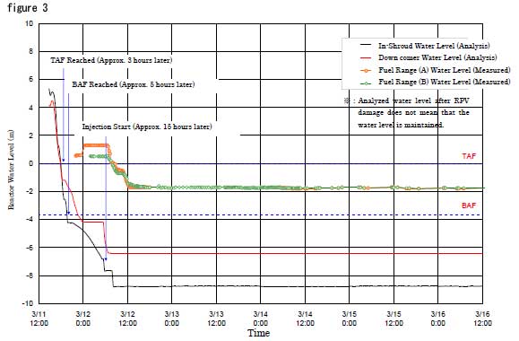
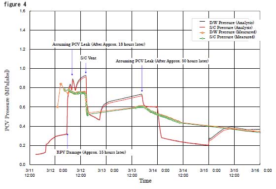
As a result, as the meltdown proceeded in the RPV, the high temperature, high pressure gas blasted violently out through that hole into the containment vessel. Thus the containment vessel pressure rose rapidly (Fig. 4). This is TEPCO’s ‘simulation analysis’ deception technique.
This is nothing but a ‘voodoo simulation’ in which the earthquake issue is cleverly ignored using the smokescreen of the high-speed meltdown. The undeniable gap between the actual measured values for the reactor water level and the result of the simulation is the very piece of evidence that is needed to see through this disgraceful deception.
Mitsuhiko Tanaka (Science writer; ex-RPV designer)