State of the Plant
As a result of the accident, many of the measuring instruments installed in the Fukushima Daiichi Nuclear Power Station (FDNPS) measuring system are malfunctioning. There is doubt about the accuracy of values being measured, but if these values are taken as the premise, from the temperature of the containment vessel and from the release of Xenon-135, a noble gas that is released when nuclear fission takes place, it can be estimated that the state of the reactor is stable.
However, even now 10 million Bq/hr of radioactive substances are being continually released into the atmosphere (see Figure 1). (The leakage of contaminated water will be mentioned below.)
Additionally, the Tokyo Electric Power Company (TEPCO) board of directors’ meeting on December 18, 2013 decided to decommission of Units 5 and 6, and the notification to decommission the reactors was delivered to the Minister of Economy, Trade and Industry on January 31, 2014.
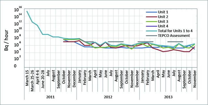 |
| Figure 1; Releases of radioactivity from Units 1 to 4 of Fukushima Daiichi Nuclear Power Station |
Current State of Post-Accident Operations
1. State of Operations concerning Molten Fuel
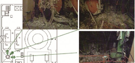
The current state is that for each of the reactors a survey of the situation inside the reactor; surveys, research and remote-control removal of debris with a view to decontamination of the buildings; surveys to reveal the locations of leaks from the containment vessels, and other work is being implemented.
2. State of Operations concerning Spent Fuel Pools
The spent fuel pools at FDNPS were badly damaged by the earthquake and accident. In the case that aftershocks cause further damage to the buildings and coolant water leaks occur from the spent fuel pools (SFPs), in which a large number of fuel assemblies is stored (Table 1), there is the possibility that fuel assemblies could melt down. Because of this, it is necessary that the fuel assemblies be removed from the SFPs and transferred to the safe common pool at the earliest possible stage.
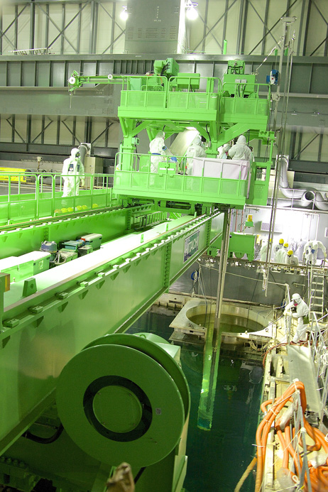
Operations to remove fuel assemblies from the SFPs have started with Unit 4. Large pieces of fallen debris in the upper part of the building and in the SFP itself have been cleared away, and removal of the fuel assemblies began in November 2013, following the construction of a cover and crane for the fuel removal operation.Elimination of debris from the upper part of the Unit 3 building is almost complete and the plan is now to implement dose reduction measures on the 5th floor of the building, the operating floor, where the dose is currently too high to allow access by human workers, and then remove large pieces of debris from inside the SFP.
In order to carry out debris removal from the upper part of Unit 1 around mid-2014, it is now planned to begin demolishing the reactor building cover currently in place, and as a preliminary to this the ventilator equipment collecting and filtering out the radioactive substances inside the building cover has been stopped since September.
Further, the dose inside Unit 2 is too high to allow inspection of the detailed situation inside the building.
For the fuel assembly removal operation, 22 fuel assemblies stored in the SFP are placed at one time in the previously existing transfer vessel used for transferring the assemblies onsite. This is then lowered a maximum of 32 m using the crane installed inside the fuel removal cover and transferred to the common pool, which is used for storing spent fuel in a separate building on the FDNPS site.
There are however, many problems with this plan. Especially grave is the fact that the repeated tendency of TEPCO to play down safety aspects due to overoptimistic assumptions are also apparent in these operations.(1)
An example is that despite the fact that what we have witnessed at FDNPS is a situation brought about by the simultaneous destruction of multiple pieces of equipment caused by the related actions of the earthquake and tsunami, TEPCO is still maintaining the single-breakdown assumption to the securing of safety in these removal operations. Moreover, we are unable to confirm an emergency contingency plan for the case where an onsite transfer vessel is dropped in the course of these operations. There are also concerns over corrosion of the fuel associated with the injection of seawater into the Unit 4 SFP at the time of the accident and over fuel damage due to debris remaining in the SFP interfering with the removal of the fuel assemblies.
There is also the problem of fuel damaged before the accident, which is still stored in the SFP. There are three damaged fuel assemblies stored in the Unit 4 SFP. These cannot be inserted into the onsite transfer vessel. TEPCO is considering ways of handling this, but one of the assemblies is seriously damaged, cracks having appeared in the channel box (the long, square metal box fitted around the fuel assembly).
In parallel with these operations, the fuel loaded into the reactor cores of Units 5 and 6 is also being transferred to the respective SFPs. The opening (removing the lid and so on of the reactor vessel) of the Unit 6 reactor began in September 2013 and the transfer of the fuel was completed on November 29.
Since the FDNPS common pool is almost completely full, from June older fuel assemblies stored there have been transferred, in order of age, to dry casks, and these have been moved to a temporary storage facility that has been newly constructed on the site.
|
Reactor |
Spent fuel pool |
Transferred fuel |
| Full storage capacity (*1) |
Stored
fuel |
% |
Spent fuel |
New
fuel |
Spent
fuel |
New
fuel |
|
Damaged fuel |
| Unit 1 |
400 |
900 |
392 |
44% |
292 |
70 |
100 |
0 |
0 |
| Unit 2 |
548 |
1,240 |
615 |
50% |
587 |
3 |
28 |
0 |
0 |
| Unit 3 |
548 |
1,220 |
566 |
46% |
514 |
4 |
52 |
0 |
0 |
| Unit 4 (as of Dec. 22, 2013) |
0 |
1,590 |
1,401 |
88% |
1,221 |
3 |
180 |
110 |
24 |
| Unit 5 |
548 |
1,590 |
994 |
63% |
946 |
1 |
48 |
0 |
0 |
| Unit 6 (as of Nov. 29, 2013) |
(*2) 0 |
1,770 |
1,704 |
96% |
1,640 |
1 |
64 |
0 |
0 |
| Common Pool |
– |
6,840 |
5,718 |
84% |
5,716 |
0 |
2 |
– |
348 |
| Temporary dry cask storage facility |
– |
(*3) 2,930 |
(*4) 1,067 |
26% |
1,067 |
0 |
0 |
– |
– |
|
Table1; State of the fuel assembly removal operation (as of Nov. 20, 2013)
(*1) However, there is some spare capacity over and above the “full storage capacity” for the number of assemblies to be loaded into the reactor core. This is for the storage of reactor core fuel during regular maintenance. (*2) Fuel assemblies in Unit 6 reactor transferred to spent fuel pool by Nov. 29, 2013. (*3) Number of installed dry casks is 23 (dry cask capacity is 50).(*4) 408 dry casks which became unusable due to the tsunami on March 11, 2011 have been transferred here from the dry cask storage building in FDNPS. Units: Number of fuel assenblies. |
 |
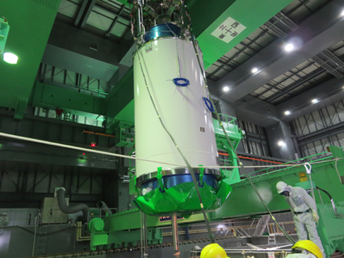 |
| Transfer vessel |
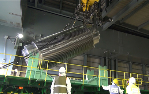 |
| Spent fuel pool |
Loading the transfer vessel onto a trailer |
| Photos by TEPCO |
3. Contaminated water problem
Measures planned against the continually increasing amounts of contaminated water are as follows: Establishment and operation of the “ground water bypass” to pump up ground water and release it into the sea; water level management by restoration of the pumping wells, that became unusable due to the accident, in the vicinity of the reactor buildings (scheduled to resume operation in mid-FY2014); construction of a water barrier on the land side of the reactors (scheduled to be usable during the first half of FY2015); waterproofing of holes and so on in the outer walls of the Unit 1 to 4 buildings (scheduled to be completed in FY2017); work to decrease the volume of contaminated water through operation of the multi-nuclide removal equipment (ALPS) (scheduled for full operation around mid-FY2013); and increased storage tank installations. However, as we have already reported in NIT156, the gravity of the situation is continuing to increase, for example, with contaminated water leakages from the water storage tanks and from the turbine buildings.
Barriers have been established around the contaminated water storage tanks, and valves have been installed to allow for the release of rainwater and so on. However, at first these valves were left permanently open out of concern that rainwater might overflow the barriers. Since the contaminated water leakage incident that took place in August 2013 the valves have been kept permanently closed, but the necessity for countermeasures in the case that rainwater overflowed the barriers was pointed out from the time when this operational change was put into effect. It was decided that water inside the barriers would be first transferred to a storage tank and then released only after the level of contamination has been confirmed. However, the preparation of hoses for the transfer of the water to tanks was not carried out smoothly, and when heavy rain occurred on September 17, rainwater overflowed the barriers, but TEPCO released the water after only a simple measurement. At first, the results of these simple measurements were said to be 2 Bq/l total beta radiation when the releases were begun, but it later became clear that this was in fact a misreading of 24 Bq/l.
Looking at the accident list (Table 2), it seems that a large number of other operational mistakes have also occurred. This gives us a very strong impression not only of the severity of the post-accident operations at FDNPS but also of the limits of TEPCO’s accident management capabilities.
(Hajime Mastukubo, CNIC)
| Date |
Location |
Content |
| July-4 |
Unit 2 CST reactor water injection system line |
When carrying out the changeover work from the elevated reactor water injection system to the CST (condensate storage tank) reactor injection system, the reactor injection line valve in the turbine building, which should normally be in the closed position, was in the open position and some of the water which should have flowed to the reactor core spray system flowed into the feedwater system. |
| July-5 |
Unit 5 D/G (B) alert malfunction lamp |
The Unit 5 emergency diesel generator B (D/G (B)) alert malfunction lamp (which shows that the D/G is not in a state of alert) came on. It is thought that this occurred due to the position of a fuel bundle shifting from its normal position. |
| July-5 |
Unit 5 D/G (B) air storage tank pressure |
It was confirmed that the pressure in the air storage tank was reduced when the Unit 5 D/G (B) was operated. It was thought that the solenoid valve pilot sheet, a consumable item, had hardened, that air was escaping from the sheet due to deformation, and that the solenoid valve was unable to close completely. |
| July-10 |
Unmanned crane removing debris from the upper part of the Unit 3 reactor building |
Hydraulic oil was confirmed to be oozing from the joint on the hydraulic hose on the hydraulic cutter on the unmanned crane being used in debris-removal work on the upper part of Unit 3 reactor building. |
| July-18 |
Center of Unit 3 reactor building 5th floor (equipment storage pool side) |
Something appearing as steam was confirmed to be drifting around in the vicinity of the center of Unit 3 reactor building 5th floor (equipment storage pool side). (This later appeared continually in low temperature, high humidity conditions.) There was no significant change seen in main plant-related parameters, monitoring posts or continuous dust monitors, or in the atmospheric dose above the reactor building spent fuel pool. |
| July-23、24 |
Dust radiation monitor in the ventilation equipment outlet in Unit 2 reactor building |
An alarm sounded indicating an abnormality in the equipment in the absorbtion pump in the Unit 2 dust radiation monitor system B and the dust monitoring B system was stopped. There was no significant change in the plant data, etc. It is thought that the dust absorption pump stopped when the alarm sounded indicating equipment abnormality due to a shift in the position detector on the (motor driven) airtight device which locks in place the dust measurement filter paper by pinching it. The equipment abnormality alarm also sounded on July 24. |
| July-25 |
Unit D/G6A |
As a test of automatic startup of the Unit 6 D/G(A), when the Unit 6 6.9 kV electricity distribution board C was shut down, the residual heat removal system B, which was cooling the reactor, ceased operation. |
| July-30 |
Second cesium absorption device (SARRY) |
The “booster pump stopped/leak detected” alarm sounded in the second cesium absorption device (SARRY), which was currently in the process of treatment operations, and shut down automatically. |
| August-10 |
Underground water storage tank Nos. 3 and 4 |
A bulge of maximum height of approxiately 40 cm and to an extent of approximately 30 m × 20 m occurred around the center of the embankment of the No.3 underground water storage tank. A buldge also occurred around the center of the upper surface of No.4 underground water storage tank, with an extent of approximately 10 m × 10 m. It is thought that the cause is the tendency for the ground water to rise in the vicinity of the underground water storage tanks since mid-July. |
| August-12、19 |
Important anti-seismic building |
An alarm sounded to indicate a high level of radiation in a continuous dust monitor at the front of an important anti-seismic building on August 12. It was confirmed that 10 out of 16 people who had boarded an onsite bus from the important anti-seismic building had bodily radioactive contamination. Two out of three people who boarded an onsite bus at the important anti-seismic building on August 19 were also confirmed to have bodily contamination. It is thought that this problem was due to dust drifting on the wind when debris was amassed and removed after removal of a ceiling crane girder during the debris removal operations in the upper part of Unit 3 reactor building. |
| August-19 |
H4 area tank |
It was confirmed that the water level in the H4 area No.5 (H4-I-5) tank had fallen by about 3 m (roughly 300 m3). It was confirmed that the wall of the drainage channel to the east side of the H4 area tank had evidence of streak-like flow marks (surface dose equivalent rate 6.0 mSv/h (gamma + beta radiation (70 μm dose equivalent rate)) and thus there was a possibility that contaminated sludge, etc. had flowed into the drainage channel. Tanks in several areas were later confirmed to have places with high radiation doses. |
| August-24 |
Gas management system of the Unit 2 reactor containment vessel |
A fall in pressure in the Unit 2 reactor containment vessel and reduction in ventilation flow of the gas management system of the reactor containment vessel occurred. The amount of radioactivity of the gas released was assessed as around 2 × 10⁴ Bq. |
| September-5 |
Large crane for debris removal on the upper part of Unit 3 reactor building |
The jib (crane arm) of the 600 ton crawler crane being used in the debris removal operations on the upper part of the Unit 3 reactor building collapsed sideways and it was confirmed that the part where the jib joins the main mast was damaged. |
| September-12 |
Units 5 and 6 RO (reverse osmosis membrane) device |
Water was discovered leaking from the Unit 5 and 6 retained water treatment device. The estimated amount of the leakage was around 65 l of water treated by the RO device.The radiation concentration of the leaked water was below the detection limit for Cs-134, 4.2×10⁻³ Bq/cm3 for Cs-137, and below the detection limit for total beta. |
| September-15 |
B South tank area dike |
Water accumulated behind the B area tank dike overflowed and the water that had accumulated behind the dike was transferred to a B area tank. The water that had overflowed had a total beta value of 37 Bq/l. The level of water behind the tank dike rose due to rain associated with an approaching typhoon on September 16. The water well below the notification criterion for Sr-90 of 30 Bq/l was released outside the tank dike (7 areas, total volume approximately 1,130 m3). Water other than this was pumped into a tank within the area (12 areas, total volume approximately 1,410 m3). |
| September-18 |
Central section of Units 1 and 2 exhaust stack |
During a seismic safety assessment of the Units 1 and 2 exhaust stack, it was confirmed that the steel material in the exhaust stacks (bents) showed damaged locations such as with subsidiary fracture, seeming subsidiary fracture or rusting. Since there are places with high dose rates in the area of these exhaust stacks, it is planned to begin an investigation after detailed investigation method, etc. has been considered. |
| October-1 |
H6 area notch tank |
When transferring rainwater behind the H6 area dike to the H2 south area dike, part way along the hose used to transfer the water the water overflowed from a notch tank. The volume of water leaked was about 5m3 and radiation in the water in the notch tank was Cs-134: 8.0 Bq/l, Cs-137: 16 Bq/l, Total beta: 390 Bq/l (Sampled on October 1). |
| October-2 |
H8 south tank area |
Due to the impact of a typhoon, the water level behind the H8 south tank area dike rose and overflowed the dike. The result of radiation measurement of the water accumulated behind the dike showed Cesium-134 and 137 to be below the detection level and total beta to be 15 Bq/l. |
| October-2 |
G3 east tank area |
It was confirmed that rainwater had reached the upper part of the dike in the G3 east tank area (welded tanks). Water that had accumulated behind the dike was transferred to a tank in the same area. Radiation measurement results showed that the water that had accumulated behind the dike had Cesium-134, 137 and total beta of below the detection limit. |
| October-2 |
B south area tank |
To prevent the overflow of rainwater from the typhoon, when rainwater behind the B south area dike was transferred to tanks in the same area and in other areas, around 17m3 of water leaked into the area behind the dike from between the roof panel and the side panel of the tank because it had been constructed on sloping land, and approximately 430 l of water leaked outside the dike. The leaked water was water that had already undergone the water conversion treatment process (total beta: 580,000 Bq/l, Cesium-134: 24 Bq/l, Cesium-137: 45 Bq/l (sampled on October 2)). It is possible that the water flowed into the sea through the gutters and drainage channels. |
| October-3 |
Unit 5 floor drain collector pump gland water outlet pipe |
Water leaked from the floor drain collector pump water outlet pipe in the Unit 5 waste treatment building. The volume of the water was approximately 500 ml. |
| October-9 |
Water conversion device RO-3 temporary house |
A leak occurred in the temporary house while during work to change to PE pipes was being carried out when the cam-lock (joint) for a pressure hose in a location other than that to be changed during the work was mistakenly removed. The volume of water leaked was approximately 7m3. |
| November-15 |
G6 south area tank |
Leakage was confirmed from the lower two tank side wall joints (flanges) of the steel tube type tank G6-C3 in G6 south area. The result of the radiation measurements was that the water dripping down and accumulating in the horizontal flat part of the flanges showed 35 mSv/h (gamma + beta (70 μm dose equivalent rate)), 0.03 mSv/h (gamma) (at a distance of 5 cm). |
| November-19 |
Emergency nitrogen gas separation device |
The air-operated valve on the emergency nitrogen gas separation device supply line failed to operate. |
| November-23 |
Nitrogen gas separation device (A) |
While running the two (A and B) Nitrogen gas separation devices, which pump nitrogen into the Units 1 to 3 reactor pressure vessels and reactor containments, the “dryer abnormal current or dryer high pressure cut” alarm sounded and the nitrogen gas separation device (A) ceased operation. |
November-26、
December-9 |
GIS interface board |
The “South 66 kV onsite transformer 2B abnormal GIS” alarm sounded and at the same time the same alarm automatically reset itself. Evidence that a small animal had entered this GIS interface board (a relay board which collates information from the control boards at the site and sends it to the switching station system) was discovered. On December 9, the alarm “South side 66 kV Okuma line 3 L light malfunction” also sounded (this alarm automatically reset). It was confirmed that a small animal had entered the interface board. |
| December-11 |
Unit 3 spent fuel pool alternative cooling system secondary system (system A) |
It was confirmed that filtered water at the rate of about one drip per five seconds was dripping from the metal flexible hose joint in the Unit 3 spent fuel pool alternative cooling system secondary system (system A). The extent of the leakage was approximately 50 cm × 40 cm. |
| December-18 |
F area C5-C6 tank connecting pipe |
It was discovered that water was leaking at a rate of approximately one drop each minute from the joint (on the C5 tank side) of the C5 and C6 tank connecting pipe in the F area tanks (north of Units 5 and 6). The extent of the dripping was approximately 30 cm × 5 cm × 1 mm (thickness). |
| December-22 |
H5, G6 tank area |
Water was confirmed to be leaking from the lower part of the dike on the west side and the seam of the dike on the northeast side of the H5 tank area. Leaks were also confirmed from the lower part of the dikes on the north and west sides of the G6 north tank area. Leaked volumes of water (volume of water that seeped into the soil) were estimated to be approximately 1.0 m3 in the northeast side of the H5 tank area and approximately 0.8 m3 in the G6 north tank area. |
| December-24 |
H4 tank area and H4 east tank area |
The water level behind the dikes in the H4 tank area and H4 east tank area fell. Leaks occurred. The leaked volume from the H4 tank area was estimated at approximately 116 m3 (Strontium-90: 20 Bq/l, Cesium-134: below detection limit, Cesium-137: below detection limit), and from the H4 east tank area the leaked volume was estimated at approximately 109 m3 (Strontium-90: 440 Bq/l, Cesium-134: below detection limit, Cesium-137: below detection limit). |
|
| Table 2; List of Accidents, July to December 2013 (Excerpted from TEPCO website and Nucia, the nuclear facility information disclosure library) |
[Note]
(1) A statement issued by CNIC concerning the removal of fuel assemblies from Unit 4 can be seen at www.cnic.jp/5475 (in Japanese)