Questioning the Obsolescence of Nuclear Power Plants — Part 3. Lawsuit to Revoke the Permits for Operating Lifetime Extensions for Takahama Units 1 & 2 and Mihama Unit 3: Problems in the Takahama Unit 1 PTS Analysis
By Takashima Takeo, Member, Working Group on Nuclear Engineering and Regulation, Citizens’ Commission on Nuclear Energy
- Introduction
On March 14, 2025, the Nagoya District Court handed down a verdict against the plaintiffs in the Lawsuit to Revoke the Permits for Operating Lifetime Extensions for Takahama Units 1 & 2 (known as “Lawsuit to Decommission Aging Nuclear Plants”). A point of contention in the lawsuit was whether pressurized thermal shock (PTS) phenomena,*1 which occur when the reactor pressure vessel (RPV) is rapidly cooled by water in an accident, was appropriately assessed or not. This article points out the errors the Nagoya District Court verdict made in the assessment of PTS phenomena and explains how we intend to rebut the original verdict in the appeal court.
*1: Pressurized thermal shock (PTS): A PTS phenomenon takes place when rapid cooling occurs in the pressurized reactor pressure vessel (PRV) due typically to the safety injection water fed in by the emergency core cooling system (ECCS). The stress due to the rapid cooling is superimposed on the stress due to internal pressure, exposing the internal surface of the vessel to an extremely high tensile stress. The steel vessel, which has long been exposed to neutrons generated by atomic fission during years of operation, may suffer brittle breakdown.
- Witness examination
On May 10, 2024, I delivered evidence concerning PTS as a witness on the side of the plaintiffs at the 32nd oral proceeding of the lawsuit. The following summarizes my presentation in the direct examination.
In the examination, I was asked about and answered such points as: “PTS phenomena and heat transfer coefficient,”*2 “validity of the method used to determine heat transfer coefficients specified in the regulatory code,” “the calculation by the witness of critical fracture toughness and PTS curves,”*3 and “the relationship between the cladding and PTS curves.”
One of the points I advocated through my testimony was the injustice that, while the regulatory code*4 to be followed to assess PTS phenomena (JEAC*5 4206-2007) does not mention cladding,*6 the operator treated cladding arbitrarily in the assessment and the regulatory body accepted it (very possibly did not notice it). I stated with special emphasis that the reactor operation should be discontinued because the stress intensity factor KI*7 may exceed the critical fracture toughness KIc*8 of the PRV material at the time of rapid cooling. I present the calculation results that prove this later in this article.
I testified regarding the poor assessment practice: The code based on which the regulatory body (Nuclear Regulation Authority) administers operators lacks the required specifications. The body had inquired with the organization that established the code (Japan Electric Association) about how to handle the cladding. It was as if the judiciary had inquired with the lawmaking body (the national assembly) about how to interpret a law. This was a typical example of “regulatory capture” mentioned in the report of the National Diet of Japan Fukushima Nuclear Accident Independent Investigation Commission.
*2: The heat transfer coefficient h is the factor that represents how easily heat transfers between cooling water and the RPV surface. The coefficient varies depending on the fluid type and velocity, but is independent of the temperature difference between them.
*3: A PTS curve represents the values that encourage the development of an assumed crack based on generated stresses. It is drawn in the form of the distribution of time, temperature, or thickness direction.
*4: The code established by the Japan Electric Association and endorsed by the national government (NRA). The Japan Electric Association is an organization composed of industrial, administrative, and academic sectors. It is in fact a body that establishes codes that are convenient for nuclear power operators.
*5: The Japan Electric Association Codes (JEAC) are technical standards issued by the Japan Electric Association. JEAC 4206-2007 is titled “Method of Verification Tests of Fracture Toughness for Nuclear Power Plant Components.”
*6: The cladding is a 5 to 10 mm thick stainless-steel lining deposit-welded on the internal surface of the RPV.
*7: KI represents the severity of the stress and strain exerted on a crack tip.
*8: KIc represents the strength of a component against an assumed crack.
- Fracture mechanics and stress intensity factor
In this section I would like to explain the relationship between fracture mechanics and stress intensity factor.
In fracture mechanics, which evaluates structural element breakdowns due to cracks or for other reasons, it is important to evaluate the stress*9 exerted at a tip of an assumed crack.
As an example, a penetrating straight crack, whose length is 2a, is assumed to exist on an infinite plane on which the tensile stress σ0 is exerted in the directions indicated by the arrow marks shown in Fig. 1.
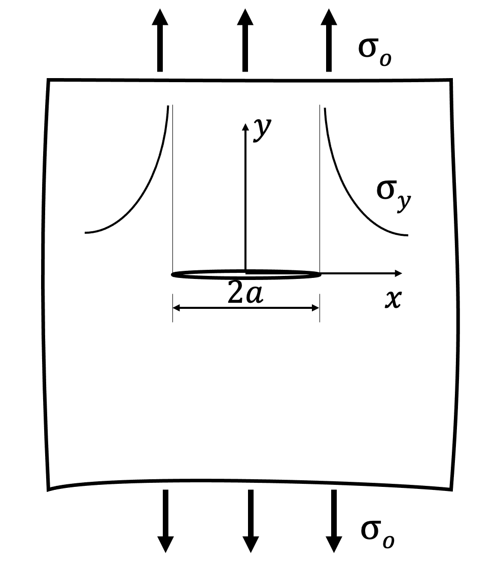
Fig.1. Infinite Plane Exposed to Uniform Tensile Stress σ0
The stress is evaluated based on the stress distribution*10 near the tip of the crack, instead of the stress at the tip, where the stress is infinite. In-plane stress distribution σy(x) is known to be inversely proportional to x1/2, where x is the distance from the crack tip. It can be expressed as follows, with the proportionality coefficient K:
(1)
where, the proportionality coefficient K is called the stress intensity factor.
The stress intensity factor K varies depending on the size, shape and direction of the crack, as well as on the stress exerted on the component. The deformation at the crack tip may be in one of three modes that are independent of each other. One of the three modes is mode I, in which the crack is being opened by tension. The stress intensity factor in mode I is KI (keɪ wʌn). Its unit is Pa・m1/2.
In other words, fracture mechanics determines whether destruction will take place or not, based on the critical fracture toughness KIc, which represents the resistance value against the growth of the crack of the structural element, and stress intensity factor KI , which is determined by the stress exerted on the structural element. An RPV is exposed to great thermal stress due to rapid cooling at the time of an accident, and when KI is greater than KIc (KI > KIc), the structural element breaks down. While KIc lowers with aging, the KI value is constant.
*9: Refers to force per unit area generated by pressure inside the structural element.
*10: Stress distribution shows stress differences depending on location.
- PTS evaluation procedure
(1) Determination of the extent of LOCA*11
Accidents vary in scale, but for the evaluation, the large-break LOCA model should be used, because the stress intensity factor KI can be estimated to be at a maximum in this model.
(2) Determination of boundary conditions for pressure and temperature in the RPV
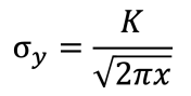
The boundary conditions are determined depending on the scale of the LOCA. In the case of a large-break LOCA, the boundary conditions are assumed to be as shown in Fig. 2.
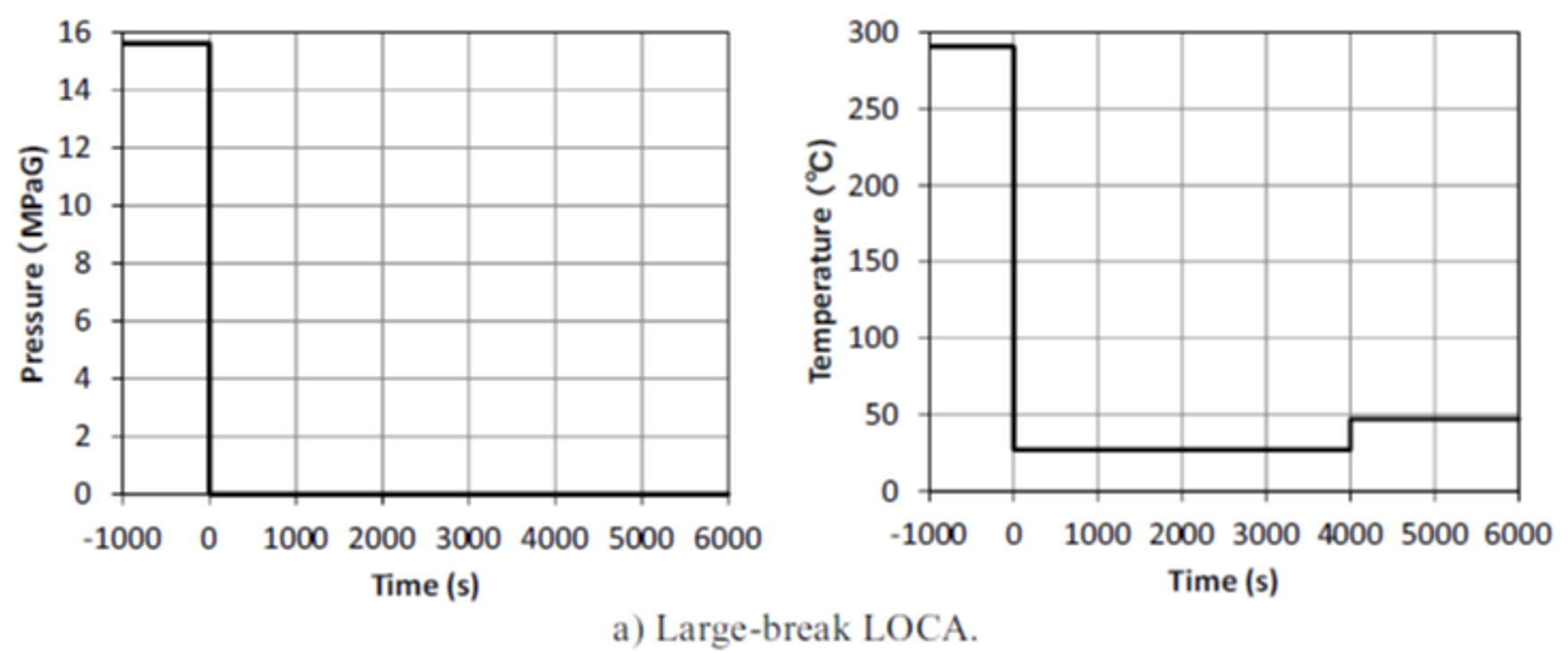
Fig. 2. Changes in Pressure and Temperature Conditions in the Vessel after the Occurrence of a Large-break LOCA
It should be noted that the temperature in this diagram is a representative temperature of the main current of the cooling material (water) and is not RPV surface temperature.
(3) Calculation of temperature distribution in the RPV base material
The temperature distribution of the base material of the RPV internal surface cooled by cooling water from the emergency core cooling system (ECCS) is calculated by differentiating the one-dimensional unsteady heat conduction equation*12 in the cylindrical coordinate system and by conducting numerical analysis.*13
The temperature distribution is a function of time and location (radial).
As shown in Fig. 3, the cladding, whose heat conduction rate is lower than that of the base
Fig. 3. Calculated Temperature Distribution and Stress Distribution of Cladding and Base Material to a Depth of 5 cm (t = 600 s)
material, works as insulation material and reduces the temperature distribution of the material. On the other hand, the cladding is exposed to a greater thermal stress than the base material. The actual reactor is provided with cladding, but JEAC 4206-2007 does not mention cladding at all. To ensure a conservative assessment, the cladding should thus not be considered. However, the operator’s calculation considers cladding.
Only when cladding is not considered and the heat transfer coefficient h is given as a constant can the equation be solved analytically, enabling the calculation of temperature distribution. However, when cladding is considered, the equations should be formulated individually for the cladding and base material, and in that case numerical analysis is used for the calculation of temperature distribution.
If the heat transfer coefficient is not a constant (when it is given as a function of time or temperature), the calculation is nonlinear, and thus numerical calculation is used to calculate temperature distribution because analytical calculation is impossible no matter whether the cladding exists or not.
(4) Calculation of base material thermal stress distribution
To evaluate PTS, circumferential thermal stress distribution σθ(r) is critical. The thermal stress distribution is calculated by means of the thermal stress basic equation and temperature distribution.*14 The thermal stress is a function of time t and location r. When it is positive, the stress is tensile, when negative, compressive.
In the evaluation of stress distribution, the thermal stress on cladding is treated as null, probably because JEAC 4206-2007 does not mention cladding. However, in the calculation by the operator, who counts in the existence of cladding in the calculation of temperature distribution, the distribution of stress in the cladding seems uncounted, because the design and construction standard (PVB-3420) specifies “cladding should not be considered as a reinforcing component.” In addition, the regulatory code does not consider the residual stress in the base material that is generated when the plate material is welded and the cladding is installed.
(5) Determination of the form, location and distribution of a virtual crack
Fig. 4 shows various crack models.*15 Crack shapes are elliptical or semielliptical.
Fig. 4. Various Crack Model
JEAC 4206-2007 specifies a semielliptical model 60 mm in length and 10 mm in depth. The crack is assumed to be parallel to the z axis and in the cylindrical part of the PRV.
When there is cladding, two types of cracks are modeled: Illustration c) in Fig. 4 represents a crack under the cladding, and illustration d) in Fig. 4 shows a crack on the surface. In the regulatory code, such a crack is designated “surface crack” (as shown in illustrations a) and d) in Fig. 4).
(6) Calculation of stress intensity factor KI
The stress intensity factor is calculated by the equation shown in F-3200 in Appendix F, “Stress Intensity Factor,” to JEAC 4206-2007. Assuming that there is cladding, I calculated the stress exerted on the cladding as well as the stress intensity factor according to the instructions in Appendix D to IAEA-TECDOC.*16
(7) Comparison between stress intensity factor KI and the critical fracture toughness KIc
The PTS curve is drawn by plotting time-based changes in stress intensity factor KI from the start of cooling in a diagram where the vertical axis is KI and the horizontal axis is temperature at the crack tip. The curve is evaluated in comparison with the curve of temperature-based changes in the critical fracture toughness KIc.
Fig. 3. Calculated Temperature Distribution and Stress Distribution of Cladding and Base Material to a Depth of 5 cm (t = 600 s)
Fig. 3 shows the calculation results of temperature distribution and stress distribution in the cladding and in the base material to a depth of 5 cm from the base material surface at 600 seconds from the start of cooling. Fig. 5 shows calculated differences in the stress intensity factor when cladding is considered and when not considered. The solid line (①) considers cladding, the dotted line (②) represents the case where cladding is considered in the calculation of temperature
Fig. 5. Impact of Cladding on KI (h = 2 kW/m2K, Semi-elliptic Crack on Surface)
distribution, but the stress in the cladding is ignored, and the chained line (1) shows calculation results that take thermal stresses in the cladding into consideration.
I previously found that KI in Fig. 5 (1) was closely consistent with the results by Meshii,*17 where the heat transfer coefficient h ranges from 1 kW/m2K to infinity.
On the condition that there is no cladding, as in the solid line (1), the line shows a critical crossing with the fracture toughness value curve at the time of 60 years of age, while the dotted line (2) shows no critical crossing, indicating that KI is smaller. Thus it is no exaggeration to say that the temperature distribution determines stress distribution and stress intensity factor KI. Therefore, the operator’s method, where temperature changes were made smaller by considering cladding in the temperature distribution calculation and thus lowering stress distribution and KI, is highly malicious.
The operator reckons that cladding works as insulation material when calculating RPV temperature changes during cooling. However, when calculating the intensity factor of the generated stress, the operator does not consider the cladding. This inconsistent treatment of cladding is surprising and can in no way be considered reasonable.
Table 1 qualitatively summarizes the KI results that are different depending on the extent cladding is considered.
Table 1. Treatment of Cladding and the Results of PTS Analyses under Different Crack Conditions
*11: LOCA stands for Loss of Coolant Accident.
*12: The one-dimensional unsteady heat conduction equation can be derived easily from Fourier’s law and the law of conservation of energy in a small portion of an object.
*13: Kyushu Electric Power Company, “Response to the Committee Members’ Comments on the RPV Embrittlement Degradation Resulting from Neutron Irradiation (Kyushu Electric Power Company),” Document 2 presented at the 12th Hearing Meeting on the Technological Assessment of Reactor Aging, p. 4.
*14: Ibid., p. 5.
*15: IAEA-TECDOC-1627 (2010), p. 31.
*16: Ibid., p. 172.
- Two PTS-related grounds for appeal
5.1 No mention of cladding in JEAC 4206-2007
I plan to point out that the Nagoya District Court verdict is unreasonable in that it regards the operator’s evaluation as being compliant to the code. The verdict gives the judgment that: “It cannot be concluded that JEAC 4206-2007 prohibits the consideration of cladding in thermal conduction analysis because the code does not mention the cladding. In that the RPV surface is provided with cladding, it cannot be said that considering cladding in thermal conduction analysis is unreasonable.”*18 The verdict states in the section preceding this statement that the Japan Electric Association, which established JEAC 4206-2007, answered that it does not specify requirements concerning cladding in JEAC 4206-2007, but the code does not prohibit analysis that takes cladding into consideration (reply from the Japan Electric Association),*19 as one reason for this verdict. However, as the appeal brief states, this reply from the Japan Electric Association was obtained while the District Court lawsuit was ongoing, namely, when the plaintiffs (appellants) pointed out that, while JEAC 4206-2007 does not mention cladding, the operator has reckoned the cladding into the temperature distribution analysis, thus deliberately easing the temperature distribution. This was the first time that the NRA had confirmed the operator’s reckoning of the cladding. This confirmation was delivered not even when the administrative proceedings for the superannuated reactors were being conducted. The confirmation is simply superficial and does not constitute any ground for allowing a conservative interpretation of the code. Rather, this confirmation by itself discloses a negligence or insufficient assessment by the NRA in its assessment processes concerning the impact of cladding on the stress intensity factor.*20
5.2 Different models for the calculation of temperature distribution and stress distribution
As the verdict mentioned, even if cladding is actually provided, assessment code JEAC 4206-2007 specifies a “surface crack” as an assumed failure, and it is against the code and unacceptable to consider a crack under the cladding as a subsurface crack such as that shown in illustration c) in Fig. 4. Further, if the fact that the cladding exists can be the ground for considering the cladding in thermal conduction analysis, it is unreasonable not to consider cladding in stress analysis. Because of this very reason, the analyses should be performed consistently without taking cladding into consideration. If cladding should be considered, stress analysis should also be performed by taking into consideration the stress in the cladding.
*17: MESHII Toshiyuki, “Genkai Unit 1 Provisional PTS Analysis Calculation.” “The 14th Hearing Meeting on the Technological Assessment of Reactor Aging (May 9, 2012),” Document 8.
*18: “Verdict in the Lawsuit to Revoke the Permits for Operating Lifetime Extensions for Takahama NPS Units 1 and 2,” p. 327, drive.google.com/file/d/1FHtn-FtIimh2FiugjhvI5ZIv4p6BF5yf/view.
*19: Ibid., p. 327.
*20: Section (5), “Neutron irradiation” in “Appeal Brief in the Lawsuit to Revoke the Permits for Operating Lifetime Extensions for Takahama NPS Units 1 and 2,” p. 85.
drive.google.com/file/d/1WaPE89sZhfaNbqaAcveLp-uNuZ1Ou5Vt/view
- Conclusion
I plan to testify that I calculated stress intensity factor according to the instructions given in JEAC 4206-2007 and found that the results were in agreement with calculation results by other researchers and the results by the intervener (Mitsubishi Heavy Industries) under the conditions claimed by the plaintiffs. Further, in the appeal court, I intend to show the reports and papers that indicate that the thermal stress in the cladding increases stress intension factor and argue that it is qualitatively apparent that calculating the stress intensity factor in consideration of cladding is unsafe.
